Summary
Chronic total occlusion intervention (CTO PCI) has been maturing with the advent of dedicated equipment. Simultaneously coronary Imaging modalities have evolved rapidly over the decades, application of the technologies are more demanding, as the current daily practice in CTO PCI becomes more complicated. Non-invasive imaging is central to the evaluation of ischaemia and myocardial viability which are pre-requisites for the selection of appropriate patients for CTO-PCI. In addition, computed tomographic coronary angiography can evaluate anatomical features not apparent on conventional invasive angiography as well as predict the complexity and likely success of guidewire passage during PCI. During CTO PCI intravascular ultrasound has been used increasingly to improve the quality of intervention particularly in the presence of complex anatomy.
Nuclear Test
Single Photon Emission Computed Tomography (SPECT) is used for assessing the extent of ischemia and the presence of viability of the CTO region [11. Maes AF, Borgers M, Flameng W et al. Assessment of myocardial viability in chronic coronary artery disease using technetium99m sestamibi SPECT: correlation with histologic and positron emission tomographic studies and functional follow-up. J Am Coll Cardiol. 29(1), 62–68 (1997). ]. Localization of ischemia/viability is a strong point of SPECT, while Exercise Tolerance Test(ETT) remains widely adopted screening test for detecting ischemia if the subject can exercise adequately without baseline LBBB pattern.
Positron Emission Tomography (PET) is a gold standard of detecting myocardial viability, using fluorodeoxyglucose. Because of high inventory cost and similar diagnostic accuracy to SPECT, the use of SPECT is not widely adopted on daily practice [22. Srinivasan G, Kitsiou AN, Bacharach SL et al. 18Ffluorodeoxyglucose single photon emission computed tomography: can it replace PET and thallium SPECT for the assessment of myocardial viability?. Circulation. 97, 843–850 (1998). ].
Cardiac Magnetic Resonance Imaging (CMRI)
CMRI is, currently, a test of choice to assess the viability of the myocardium in interest, identifying the area and functionality. Late myocardial enhancement of wall thickness < 25% is a marker of viability, while > 50% is more suggestive of non-viability [33. Cheng AS, Selvanayagam JB, Jerosch-Herold M, van Gaal WJ, Karamitsos TD, Neubauer S, Banning AP. Percutaneous treatment of chronic total coronary occlusions improves regional hyperemic myocardial blood flow and contractility: insights from quantitative cardiovascular magnetic resonance imaging. J Am Coll Cardiol Interv. 1, 44–53 (2008). ]. Gray zone does exist, however, regarding the late enhancement between 25-75% of wall thickness. Low dose dobutamine stress will enhance viability detection and refine indication of revascularization on the question [44. W Krahwinkel, T Ketteler, J Wolfertz, J Godke, I Krakau, LJ Ulbricht, W Mecklenbeck, H Gulker. Detection of myocardial viability using stress echocardiography. Eur Heart J. 1997(Suppl D), D111–D116. ].
OCT
Optical Coherence Tomography (OCT) system is emerging for visualizing the endoluminal surface of the vessel, stent (mal)apposition, thrombus formation, and ruptured plaque among others [55. Bezerra HG, Costa MA, Guagliumi G, Rollins AM, Simon DI. Intracoronary optical coherence tomography: a comprehensive review. J Am Coll Cardiol. 2(11), 1035–1046 (2009). ], its application for CTO-PCI is somewhat limited since the current system requires pressurized contrast or saline injection to visualize a target segment.
IVUS Application in CTO-PCI
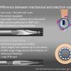
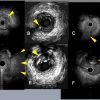
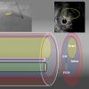
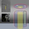
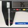
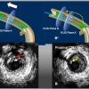
The IntraVascular UltraSound (IVUS) has played a major role in imagining the “ inner side” of the target vessel, ranging from the vessel diameter, amount of plaque distribution, the severity of calcification, the degree of remodeling, the degree of dissection, hematoma formation, and subintimal wire passage during PCI. Currently, there are two kinds of IVUS systems: a mechanical scan type with a lower profile catheter (Atlantis and Opti cross, Boston, USA , Naviocus, Altaview Terumo, Japan, Revolution, Volcano, Philips) and a solid-state phased array scan (Eagle eye, Volcano, Philips, Holland) ( Figure 1 ) [66. Vince DG, Davies SC. Peripheral application of intravascular ultrasound virtual histology. Seminars in Vascular Surgery, Vol 17. 2004: 119-125. ]. While mechanical Opticross can provide high detailed axial resolution image ( 35-50 micro), solid state of Eagle Eye provides images of 60-170 micron. IVUS in daily practice is limited worldwide due to its reimbursement issue, a Solid-state IVUS (an Eagle Eye, Volcano, Philips) with a short tip is, nonetheless, preferred for imaging during CTO-PCI, as it minimizes the extent of dissection inside of CTO. When IVUS is used for locating a proximal cap with a large side branch, IVUS pull back from a wired branch is applicable for both systems.
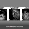
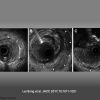
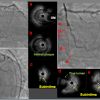
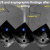
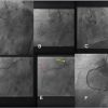
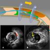
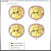
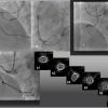
It is highly recommended that one goes through the dedicated references to obtain the basic IVUS principles and interpretation of the images in the context of clinical scenarios, which are beyond the scope of the chapter [77. Nissen S, Yock P. Intravascular ultrasound: novel pathophysiological insights and current clinical applications. Circulation. 103, 604–616 (2001). ]. Representative IVUS definition and findings on CTO PCI are shown in Figure 2, Figure 3, Figure 4 [88. Tsujita K, Maehara A, Mintz GS, Kubo T, Doi H, Lansky AJ, Stone GW, Moses JW, Leon MB, Ochiai M. Intravascular ultrasound comparison of the retrograde versus antegrade approach to percutaneous intervention for chronic total coronary occlusions. JACC Cardiovasc Interv. 2009:846-54. , 99. Lei Song, Akiko Maehara, Matthew T Finn, Sanjog Kalra, Jeffrey W Moses, Manish A Parikh, Ajay J Kirtane, Michael B Collins, Tamim M Nazif, Khady N Fall, Raja Hatem, Ming Liao, Tiffany Kim, Philip Green, Ziad A Ali, Candido Batres, Martin B Leon, Gary S Mintz and Dimitri Karmpaliotis. Intravascular Ultrasound Analysis of Intraplaque Versus Subintimal Tracking in Percutaneous Intervention for Coronary Chronic Total Occlusions and Association With Procedural Outcomes. JACC. 2017:1011-1021. ].
Practical application of IVUS in antegrade CTO-PCI
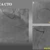
- Clarification of ambiguous proximal cap and navigate a wire intraplaque puncturing, especially with a LAD CTO at a large side branch ( Figure 5, Figure 6a, and Figure 6b )
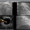
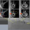
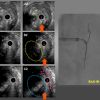
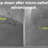
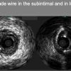
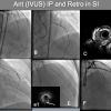
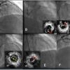
- Re-routing a wire to an intraplaque from subintimal wiring before developing a large hematoma ( Figure 7, Figure 8, Figure 9 ) [1010. Matsubara T, Murata A, Kanyama H, Ogino A. IVUS-guided wiring technique: a promising approach for the chronic total occlusion. Catheter Cardiovasc Interv. 2004:381–386. , 1111. Ito S, Suzuki T, Ito T et al. Novel technique using intravascular guided guidewire cross in coronary intervention. Circulation. 2004:1088–1092. ], since stenting over the subintimal outflow results in devastating consequences.
- Evaluation of reference Vessel Diameter (RVD) of occlusion, degree of calcification, and need for debulking ( by Rotational atherectomy or Laser system) before stenting, since some IVUS probes (Alta-view Terumo, Japan, and Opti-cross, Boston Scientific, USA) are such a low profile mechanical scan, information regarding severity of calcification could be obtained after a 1.5 mm balloon inflation up to 8-10 atm.
- Recognition of the distal end of the hematoma extension.
- Stent optimization including landing zone both proximal and distal, and recognition of stent edge dissection.
Comments
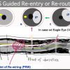
- Re-entering (Re-routing) a guide wire into an intraplaque from Subintima requires following steps: [1010. Matsubara T, Murata A, Kanyama H, Ogino A. IVUS-guided wiring technique: a promising approach for the chronic total occlusion. Catheter Cardiovasc Interv. 2004:381–386. , 1111. Ito S, Suzuki T, Ito T et al. Novel technique using intravascular guided guidewire cross in coronary intervention. Circulation. 2004:1088–1092. ].
- Requirements of IVUS application include an 8 F guide catheter, a mechanical scan type IVUS (Atlantis and Opti cross, Boston, USA , Naviocus, Altaview Terumo, Japan, Revolution, Volcano, Philips,Holland) and a solid-state phased array scan (Eagle eye, Volcano, Philips, Holland) ( Figure 1 ), a microcatheter such as a Finecross (130cm, Terumo,Tokyo,Japan) ,a Corsair Pro (135cm, Asahi Intecc, Nagoya, Japan), Caravel 135cm (Asahi Intecc, Nagoya, Japan), Turnpike LP(135cm) (Teleflex, USA) and stiffer, guide wires such as Gaia 3 rd, (Asahi Intecc, Nagoya, Japan ), Gaia Next 3 (Asahi Intecc, Nagoya, Japan), and Confianza Pro 9 or 12 (Asahi Intecc, Nagoya, Japan), and Hornet 14 (Boston, MA, USA).
- Once the first wire was confirmed in subintimal space on multiple projections by contra-lateral injection or IVUS and low possibility of antegrade dissection re-entry (ADR), Parallel wiring, or retrograde
- Disconnect an injection syringe from an antegrade system, since inadvertent injection can cause more extensive dissection and hematoma propagation.
- Before IVUS interrogation, a 1.25 to 1.5mm balloon dilation at 3-6 atm allows smooth advancement of the IVUS probe.
- In IVUS pull back, locate a point of wire deviation ( from a Subintimal space (SIS) to an Intimal Plaque (IP) about fluoroscopic projection. Record pull-back IVUS from a bit distal SIS to IP and store fluoroscopic images (simultaneously).
- Advance a 2 nd wire on a microcatheter, (most likely on a Corsair Pro, Turnpike PL, or a Finecross 135 cm with an Eagle Eye (Volcano, Phillips, Holland), and locate the wire in IVUS.
- Find a particular fluoroscopic direction on an IVUS image, which will derive from the wires, side branches, and other anatomical landmarks of the IVUS images. Some occasion, additional side branch wire may help in orienting IVUS-fluoroscopic relation.
In Figure 7, if the CTO assumed LAD and longitudinal figure (D) assumed close to the projection of RAO, a Red arrow in IVUS illust B indicates RAO, which shows a green arrow in 3 o'clock LAD direction. Bi-plane Cine-fluoro machine will facilitate wiring hereafter.
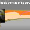
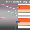
- Navigate and rotate a stiff wire of Confianza Pro 12 (or Gaia 3 rd) with a 2-3 mm sharp bend (60-90 deg, depending upon the angle, eccentric IP location), from point A to point B, while keeping the IVUS at the level B.
- In RAO projection, a 2nd wire should locate below IVUS, while orthogonal view (LAO, a green arrow), a 2nd wire has to find an overlapping position.
- When the wire tip locates IP in IVUS level B, C, advance the microcatheter and a wire deeper and confirm the IVUS that they remain in IP.
- change the guide wires to UB3g or XT-R with a short minimal curve and advance to the distal.
- confirm the distal wire position by contra-lateral injection and a small balloon (1.25 -1.5mm) dilation throughout the CTO segment.
- interrogate IVUS to check the distal reference vessel and CTO segment if dissection or hematoma extended and to measure the proximal and distal vessel reference size.
- Additional larger balloon dilation and DES deployment.
- Since CTO segment tends to require more extended coverage by DES, optimal sized Non-compliant balloon dilation is mandatory. IVUS helps in gaining DES optimization throughout the stented segment.
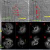
Further detailed cases are presented in detail in Figure 8b, Figure 8b, Figure 8c and Figure 9a, Figure 9b, Figure 9c, Figure 9d, Figure 9e, Figure 9f, Figure 9g, Figure 9h, Figure 9i, Figure 9j and Figure 9k.
IVUS Roles in Retrograde approach
IVUS is very much useful in:
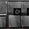
- Confirmation of Guidewire position in either IP, SIS ( Figure 10 ), or extra-vascular space.
- Optimal balloon size for wire entry in reverse Controlled Antegrade Retrograde Subintimal Tracking (CART).
- The optimal location for reverse CART
- Optimal sizing of the balloon, stent, length of the stent, and confirmation of large branch take-off ( either from intact true lumen or dissection/hematoma filled lumen)
Since reverse CART ( Antegrade balloon inflation for retrograde wire (re)-entry to the true proximal lumen) is the most commonly used technique for retrograde dissection approach (RDR), followed by direct wire crossing (conceptually, retrograde wire escalation=RWE), kissing wire technique (KW), and just-marker technique (JM), since the application of IVUS facilitated Reverse CART [1212. Rathore S, Katoh O, Tuschikane E, Oida A, Suzuki T, Takase S. A novel modification of the retrograde approach for the recanalization of chronic total occlusion of the coronary arteries intravascular ultrasound-guided reverse controlled antegrade and retrograde tracking. JACC Cardiovasc Interv. 2010:155-64. ], many modifications have reported such as Guide catheter Extension Reverse CART, stent-assisted reverse CART, and confluent balloon Reverse CART (refer to the chapter in Retrograde CTO PCI).
More recently, to avoid misunderstanding, and miscommunication among the operators, a group of CTO experts has classified the subtypes of reverse CART method, such as conventional, directed, and extended [1313. Matsuno S, Tsuchikane E, Harding SA, Wu EB, Kao HL, Brilakis ES, Mashayekhi K, Werner GS. Overview and proposed terminology for the reverse controlled antegrade and retrograde tracking (reverse CART) techniques. EuroIntervention. 2018:94-101. ]. This classification provides not only the technical interests but also a priority of the plan to choose in a case of difficulties.
Guide catheter extension reverse CART
( Figure 12 )
When there are difficulties encounter in RDR, one of the methods to apply without IVUS is a Guide-catheter extension (GCE) assisted reverse CART. With a deep sitting of GCE inside CTO, a proximal cap is shifted to the GCE tip, to facilitate reverse CART [1414. Abdul M Mozid, John R Davies, James C Spratt. The Utility of a Guideliner catheter in the retrograde percutaneous coronary intervention of a chronic total occlusion with reverse CART- the "Capture" technique. Catheter Cardiovasc Interv. 2014;83:929-932. ]. Once the wire gets into a GCE, a retrograde microcatheter can advance over a retrograde trapping wire, and once the mico catheter or an extension inside, the wire can change to an externalization wire (such as RG3 or R 350). The technique can minimize the risks associated with an RDR induced left main trunk sub-intimal wiring in the CTO involving a LAD or LCX ostium, since a GCE, once engaged deeper into the LAD or LCX can isolate and modify the proximal cap deeper, therefore, can avoid the wire crossing through the SIS before a left main trunk-LAD- LCX bifurcation .
How can IVUS resolve any difficulty of wire (re) entry encountered in a retrograde approach?
- Use of a small balloon dilatation (1.5mm) down to an overlapping segment with a retrograde approach.
- Locate an antegrade wire and a retrograde wire in SIS or IP, respectively.
- Either both wires are in SIS or IP, optimally sized balloon (according to IVUS) can complete reverse CART.
- More difficulties have been noted for an antegrade in SIS and a retrograde in IP, or in the setting of an antegrade in IP and a retrograde in SIS. IVUS can facilitate Guide wiring and locate an optimal site for reverse CART.
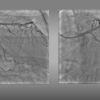
See further details in Figure 13a, Figure 13b, Figure 14a, Figure 14b, Figure 15 [1515. Galassi AR, Sumitsuji S, Boukhris M, Brilakis ES, Di Mario C, Garbo R, Spratt JC, Christiansen EH, Gagnor A, Avran A, Sianos G, Werner GS. The utility of Intravascular Ultrasound in Percutaneous Revascularization of Chronic Total Occlusions: An Overview. JACC Cardiovasc Interv. 2016: 1979-1991. ].
Evidence so far
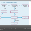
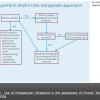
IVUS use of current CTO-PCI have played a vital role in safety (resolving proximal cap ambiguity, wire position in SIS or IP, the extent of dissection and hematoma), efficiency (navigating wires both antegrade and retrograde approaches) and long-term durability ( re-entry to IP, optimize IP tracking, and stent optimization). The benefits of IVUS-guided PCI has not yet proven on clinical outcomes in a large scale, randomized, multicenter trial, but on the expert hands, IVUS guidance has improved the quality and outcomes of CTO-PCI ( Figure 16a, Figure 16b ). Current approaches of algorithmic CTO suggest broader applicability of IVUS on crucial decision-making step [1616. Gerald S Werner. Use of Intravascular Ultrasound in the assessment of Chronic Total Occlusion. Radcliffe Cardiology. 19 9 2018. , 1717. Brilakis ES, Grantham JA, Rinfret S, Wyman RM, Burke MN, Karmpaliotis D, Lembo N, Pershad A, Kandzari DE, Buller CE, DeMartini T, Lombardi WL, Thompson CA. A percutaneous treatment algorithm for crossing coronary chronic total occlusions. JACC Cardiovasc Interv. 2012:367-379. , 1818. Harding SA, Wu EB, Lo S, Lim ST, Ge L, Chen JY, Quan J, Lee SW, Kao HL, Tsuchikane E. A New Algorithm for Crossing Chronic Total Occlusions From the Asia Pacific Chronic Total Occlusion Club: A percutaneous treatment algorithm for crossing coronary chronic total occlusions. JACC Cardiovasc Interv. 2012: 367-79. ].
Use of IVUS has increased from 2.9% of 2011 European Registry (ERCTO) to 38% of 2016 US registry (19,20). In the latter registry, among the IVUS guided group (N_234), the main focus of IVUS was stent sizing (26.3%) and optimization (38%), followed by guide wiring, proximal cap puncturing, and guide reverse CART ( Figure 17 ) [2020. Karacsonyi J, Alaswad K, Jaffer FA, Yeh RW, Patel M, Bahadorani J, Karatasakis A, Danek BA, Doing A, Grantham JA, Karmpaliotis D, Moses JW, Kirtane A, Parikh M, Ali Z, Lombardi WL, Kandzari DE, Lembo N, Garcia S, Wyman MR, Alame A, Nguyen-Trong PK, Resendes E, Kalsaria P, Rangan BV, Ungi I, Thompson CA, Banerjee S, Brilakis ES. Use of Intravascular Imaging During Chronic Total Occlusion Percutaneous Coronary Intervention: Insights From a Contemporary Multicenter Registry. J Am Heart Assoc. 2016:5(8). ]. Despite higher complexity of IVUS guided group vs no-IVUS group (J-CTO score: 2.86±1.19 vs 2.43±1.19, P=0.001), both achieved similar technical (92.8% versus 89.6%, P=0.302) and procedural success (90.1% versus 88.3%, P=0.588) and similar incidence of MACE (2.7% versus 3.2%, P=0.772).
In a 2015 report, the patients (N_230)with successful CTO wire crossing were randomly assigned to IVUS- or angiography-guided PCI. Primary endpoint was Lower in-stent late lumen loss at one year follow-up , which was significantly lower in the IVUS-guided group, compared with in the angiography-guided group (0.28±0.48 mm vs. 0.46±0.68 mm, p=0.025), with a significant decrease in restenosis of the "within-true-lumen" stent between the groups (3.9% vs.13.7%, p=0.021). The MACE were similar between the groups at two-year follow-up (21.7% vs. 25.2%, p=0.641) [2121. Tian NL, Gami SK, Ye F, Zhang JJ, Liu ZZ, Lin S, Ge Z, Shan SJ, You W, Chen L, Zhang YJ, Mintz G, Chen SL. Angiographic and clinical comparisons of intravascular ultrasound- versus angiography-guided drug-eluting stent implantation for patients with chronic total occlusion lesions: two-year results from a randomized AIR-CTO study. EuroIntervention. 2015:1409–17. ].
Kim et al. reported testing the hypothesis that IVUS-guided CTO intervention is superior to angiography-guidance in a prospective, randomized, multicenter trial. The IVUS group (n=201) or the angiography group (n=201) were allocated with secondary randomization to Zotarolimus-eluting or Biolimus-eluting stents. After 12-month, the rate of cardiac death( primary endpoint) was similar between the IVUS and the angiography groups (0% vs. 1.0%; P by log-rank test=0.16). The rates of target-vessel revascularization were not different between the groups. However, MACE (secondary endpoint) were significantly lower in the IVUS group (2.6% versus 7.1%; P=0.035; hazard ratio, 0.35; 95% confidence interval, 0.13-0.97). In the comparison between Zotarolimus and Biolimus stent, MACE rates were similar (4.0% versus 5.7%; P=0.45) [2222. Kim BK, Shin DH, Hong MK, Park HS, Rha SW, Mintz GS, Kim JS, Kim JS, Lee SJ, Kim HY, Hong BK, Kang WC, Choi JH, Jang Y; CTO-IVUS Study Investigators. Clinical impact of intravascular ultrasound-guided chronic total occlusion intervention with zotarolimus-eluting versus biolimus-eluting stent implantation: a randomized study. Circ Cardiovasc Interv. 2015;8:e002592. ].
A large scale, randomized trial is needed to substantiate the benefit of IVUS guidance, while on daily practice, selective use of IVUS will provide a practical solution for experts hands.
Long-term outcomes
See the section of CTO PCI, Antegrade approach for CTO, and ADR sections
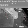
- Cardiac Magnetic Resonance Imaging becomes the central role of evaluating myocardial viability, whereas, fusion imaging of SPECT and MSCCTA provides disease anatomy and location of ischemia, simultaneously.
- IVUS plays a crucial role in CTO-PCI, especially for, 1) identifying the ambiguous proximal cap and puncturing the intimal plaque, 2) locating the intima- subintimal deviation point and navigating a second wire into the distal intimal plaque, 3) resolving the difficulty in bilateral wire (re) entry in a retrograde approach.
- IVUS assisted CTO PCI could provide better long term MACE free period in order of 2-3 years or more, compared with angiography-alone guided PCI, which raises the future direction for a need for large scale randomized multi-center trial.
Multi-slice Coronary Computed Tomography Angiography (CCTA)
CCTA has been known to possess the ability to differentiate the coronary plaque composition beyond the presence/absence or degree of calcification in comparison with IVUS and histopathology [2323. Leber AW, Knez A, Becker A, Becker C, von Ziegler F, Nikolaou K, Rist C, Reiser M, White C, Steinbeck G, Boekstegers P. Accuracy of multidetector spiral computed tomography in identifying and differentiating the composition of coronary atherosclerotic plaques: a comparative study with intracoronary ultrasound. J Am Coll Cardiol. 2004:1241-7. , 2424. Schroeder S, Kuettner A, Leitritz M, Janzen J, Kopp AF, Herdeg C, Heuschmid M, Burgstahler C, Baumbach A, Wehrmann M, Claussen CD. Reliability of differentiating human coronary plaque morphology using contrast-enhanced multislice spiral computed tomography: a comparison with histology. J Comput Assist Tomogr. 2004:449-54. ]. With an improvement of hardware and rapid development of dedicated workstation, CCTA is one of the most rapidly expanding modalities to assess on CTO, for procedural road mapping and improved result [2525. Opolski MP, Achenbach S. CT Angiography for Revascularization of CTO: Crossing the Borders of Diagnosis and Treatment. JACC Cardiovasc Imaging. 2015:846-58. ].
CTO operator can find a much of useful information in CCTA before the index PCI procedure, regarding the proximal cap ambiguity, true length of occlusion, the amount and distribution of the calcified plaques, distal vessel size, degree of remodeling, presence of collaterals and entire vessel course [2626. Werner GS, Schuhbäck A, Rixe J, Möllmann H, Nef HM, Gundermann C, Liebetrau C, Krombach GA, Hamm CW, Achenbach S. Preprocedural coronary CT angiography significantly improves success rates of PCI for chronic total occlusion. Int J Cardiovasc Imaging. 2013:1819–1827. ].
General steps to apply CTA before CTO PCI
Acquisition of the high-quality pictures is beyond the scope of the chapter, so it is highly recommended that one refers to the dedicated books on the subjects in term of acknowledging basic principles and interpretation of the images [2727. Claudio Smuclovisky. Coronary Artery CTA: A Case-Based Atlas Springer. (2011/9/30) ISBN: 1461409497. , 2828. Robert Pelberg. Cardiac CT Angiography Manual; 2nd ed. Springer. (2015/6/9) ISBN: 9781447166894. ]. All the figures in the chapter were adapted from our daily practice and recorded by the electrocardiogram-gated, heartbeat detector row CT. The gantry rotation time was 0.35-0.5 seconds in a single source, less than 0.1 seconds in a Dual source per rotation, and the slice thickness was 0.5 mm. The tube voltage was 80-120 kV on the patient condition (Aquilion ONE, Canon Medical, Japan, SOMATOM Definition, Siemens, Germany, and Revolution CT, General Electric, USA) on each institution. Oral metoprolol was administered before image acquisition for optimal heart rate unless contraindicated. Contrast injection protocol consisted of a bolus of 50-80 mL of nonionic contrast medium at a flow rate of 4 to 5 mL/s followed by an injection of 30 mL of contrast–saline mixtures and of saline 30 mL.
Obtain high-quality images of coronary arteries
The acquired data set is analyzed in the dedicated workstation by a group of technicians, radiologists, and cardiologist when ambiguity present. Image data set was reconstructed by 0.5 to 0.7 mm slices in MPR and 0.5 -20mm slices in MIP. The whole plaque is assessed by cross-sectional views with 1-mm slice to evaluate the maximal and minimal luminal area of CTO and neighboring segments.
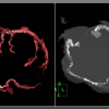
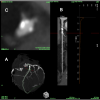
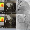
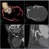
CTA Protocol should include hi-standardized images on stable hemodynamics for 3D Volume Rendering (VR), Multiple Reconstruction (MPR) and Maximum Intensity Projection (MIP), among others ( Figure 19, Figure 20, Figure 21 ).
VR provides 3-D views of the coronary anatomy showing the entire coronary tree, which displays an excellent overview of vessel anatomy outside, but not interior information.
( Figure 18 )
Angiographic view, a form of MIP images, to show a 3 D views of anatomy. As the name implies, the views can locate calcified plaque alongside the vessel course. Large epicardial collaterals could also be visualized.
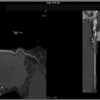
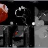
MPR provides more detailed cross-sectional information including curved tomographic and short axial views. Of note, since MPR images are reconstructed from the original data set and analyzed by software, the image axis is not sliced by long anatomical axis.
MIP, especially slab MIP, provides continuous CT images, given on a certain slab thickness. Each slice projects the intensity of each pixel and provides the maximum intensity among the continuous images. This view simulates the actual cross-section of the coronary in a given axial plane and slice width. Therefore, one image can not depict the entire length of a vessel. The most advantage of Slab MIP is capable of confirming not only the proximal cap, but also vessel course, and the distal cap by slice by slice analysis. Also, it can describe plaque characteristics, location of calcification and the degree of vessel remodeling. However, construction images are influenced by the acquisition time (vessel slice can change by heartbeats) and space (respiratory influence), so some considerations of minimizing artifacts must be required in obtaining the data set.
Motion artifact
The rapid heart rate of atrial fibrillation and inability to hold breath are two major sources of motion artifacts in obtaining CTA data acquisition. Also, the presence of heavy calcification, prior stent implantation, surgical clips, pacemaker or ICD electrodes, lesions of RCA and LCX in the presence of pericardial effusion are reported to interfere with the image reconstruction for their higher CT density or blurred motion, respectively. [2929. Ma H, Gros E, Szabo A, Baginski SG, Laste ZR, Kulkarni NM, Okerlund D, Schmidt TG. Evaluation of motion artifact-metrics for coronary CT angiography. Med Phys. 2018: 687-702. , 3030. Kondo T, Takamura K, Fujimoto S, Takase S, Sekine T, Matsutani H, Rybicki FJ, Kumamaru KK. Motion. Artifacts on coronary CT angiography images in patients with a pericardial effusion. J Cardiovasc Comput Tomogr. 2014:19-25. ]
Definition
[3131. Opolski MP, Achenbach S, Schuhbäck A, Rolf A, Möllmann H, Nef H, Rixe J, Renker M, Witkowski A, Kepka C, Walther C, Schlundt C, Debski A, Jakubczyk M, Hamm CW. Coronary computed tomographic prediction rule for time-efficient guidewire crossing through chronic total occlusion: insights from the CT-RECTOR multicenter registry (Computed Tomography Registry of Chronic Total Occlusion Revascularization). JACC Cardiovasc Interv. 2015:257-267. , 3232. Fujino A, Otsuji S, Hasegawa K, Arita T, Takiuchi S, Fujii K, Yabuki M, Ibuki M, Nagayama S, Ishibuchi K, Kashiyama T, Ishii R, Tamaru H, Yamamoto W, Hara M, Higashino Y. Accuracy of J-CTO Score Derived From Computed Tomography Versus Angiography to Predict Successful Percutaneous Coronary Intervention. JACC Cardiovasc Imaging. 2018:209-217. ]
CTO segment is defined by the complete absence of luminal enhancement.
CTO length is measured along the vessel axis
Both proximal and distal cap of CTO is described as blunt, tapered, or non-tapered or tapered.
Among the non-CTO lesions, significant stenosis is considered by diameter stenosis ≥70% in the major epicardial artery
Calcification is recognized as a white mass(es) in a cross-sectional view. Significant calcification is defined as > 50% cross-sectional area in the CTO segment.
Findings, so far, available in CCTA utilization for CTO-PCI, include:
- CCTA identifies the ambiguous proximal cap of CTO on angiography, the most detailed distribution of calcification (but tends to over-estimate the magnitude), occlusion length, tortuosities, the degree of remodeling, and vessel course. [2525. Opolski MP, Achenbach S. CT Angiography for Revascularization of CTO: Crossing the Borders of Diagnosis and Treatment. JACC Cardiovasc Imaging. 2015:846-58. ]
- Scoring on CCTA -derived JCTO score could dictate a reasonable strategy and r predict procedural success and 30-min wire crossing significantly higher than those derived from conventional angiography (0.855 vs. 0.698; p < 0.001 for procedural success and 0.812 vs.0.692; p < 0.001, for wire crossing). [3333. Yu CW, Lee HJ, Suh J, Lee NH, Park SM, Park TK, Yang JH, Song YB, Hahn JY, Choi SH, Gwon HC, Lee SH, Choe YH, Kim SM, Choi JH. Coronary Computed Tomography Angiography Predicts Guidewire Crossing and Success of Percutaneous Intervention for Chronic Total Occlusion: Korean Multicenter CTO CT Registry Score as a Tool for Assessing Difficulty in Chronic Total Occlusion Percutaneous Coronary Intervention. Circ Cardiovasc Imaging. 2017: 10(4). ]
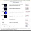
- Recent multicenter registry showed that CTA before PCI could grade the complexities of CTO to predict initial Guide wiring success < 30 min( the similar findings of J-CTO score) and the models were validated by similar cohort in another study [3131. Opolski MP, Achenbach S, Schuhbäck A, Rolf A, Möllmann H, Nef H, Rixe J, Renker M, Witkowski A, Kepka C, Walther C, Schlundt C, Debski A, Jakubczyk M, Hamm CW. Coronary computed tomographic prediction rule for time-efficient guidewire crossing through chronic total occlusion: insights from the CT-RECTOR multicenter registry (Computed Tomography Registry of Chronic Total Occlusion Revascularization). JACC Cardiovasc Interv. 2015:257-267. ]. CCTA derived RECTOR score not only helps in grading the complexities of PCI but also provides an accurate and straightforward non-invasive tool in a time efficient Guidewire crossing ( Figure 21 )
- Compared with the J-CTO score (area under the curve: 0.76), the CT-RECTOR score (area under the curve: 0.85) yielded a higher predictive value for successful GW crossing within 30 min (p = 0.0018) [3232. Fujino A, Otsuji S, Hasegawa K, Arita T, Takiuchi S, Fujii K, Yabuki M, Ibuki M, Nagayama S, Ishibuchi K, Kashiyama T, Ishii R, Tamaru H, Yamamoto W, Hara M, Higashino Y. Accuracy of J-CTO Score Derived From Computed Tomography Versus Angiography to Predict Successful Percutaneous Coronary Intervention. JACC Cardiovasc Imaging. 2018:209-217. ].
- K( Korean Multicenter Registry) CTO score with new parameters of the proximal side branch, severe calcification, whole luminal calcification, and ≥12 months or unknown duration of occlusion. Showed higher discriminative value compared with the other scoring systems (c-statistics=0.78 vs. 0.65-0.72, P<0.001, all). The sensitivity, specificity, positive predictive value, negative predictive value, and accuracy of a KCCT score of <4 for guidewire crossing ≤30 minutes was 70%, 68%, 72%, 73%, and 70%, respectively. The scoring system also showed consistent results with procedural success (P<0.05, all) [3333. Yu CW, Lee HJ, Suh J, Lee NH, Park SM, Park TK, Yang JH, Song YB, Hahn JY, Choi SH, Gwon HC, Lee SH, Choe YH, Kim SM, Choi JH. Coronary Computed Tomography Angiography Predicts Guidewire Crossing and Success of Percutaneous Intervention for Chronic Total Occlusion: Korean Multicenter CTO CT Registry Score as a Tool for Assessing Difficulty in Chronic Total Occlusion Percutaneous Coronary Intervention. Circ Cardiovasc Imaging. 2017: 10(4). ]
- When CTO collateral channels are visualized on CCTA, success in collateral wire crossing seems to be higher (74.1% vs. 46.4%, p ¼ 0.034) and fewer complication (11.1% vs. 32.1%, p ¼ 0.041) than non-visualized cohort in retrograde approach [3434. Sugaya T, Oyama-Manabe N, Yamaguchi T, Tamaki N, Ishimaru S, Okabayashi H, Furuya J, Yoshida T, Igarashi Y, Igarashi K. Visualization of collateral channels with coronary computed tomography angiography for the retrograde approach in percutaneous coronary intervention for chronic total occlusion. J Cardiovasc Comput Tomogr. 2016:128-34. ].
Whole calcified occlusion on CTA does not mean the inability to penetrate with a wire, balloon dilation, and full stent deployment. Cross-sectional analysis by 0.5-1.0mm slice on MPR image describes a possible “donuts hole” on broader CT scale windows. Once CTO is crossed, judicious use of additional rotablator, Lazer, shockwave lithotripsy will enhance successful expansion of the DES and possible long term outlook.
More recently, the augmented-reality glass integrated system (Co-registration) becomes possible in complex CTO cases, which will facilitate a procedure and allow a streamlined approach with possible better procedural results [3535. Roguin A, Abadi S, Engel A, Beyar R. A novel method for real-time hybrid cardiac CT and coronary angiography image registration: visualizing beyond luminology, proof-of-concept. EuroIntervention. 2009:648-53. ]
Current Possible Indications of CCTA before CTO-PCI
- High J-CTO Scored complex CTO
- Complex CTO, involving Aorto-Ostial region
- CTO with an anomalous coronary anatomy
- Long occlusion with moderate-severe calcification
- Prior failed attempt with cap and vessel course ambiguity and tortuosity
- PCI for a Post CABG native CTO, especially occlusion involving the anastomotic graft site
Routine use of CCTA will not be considered applicable for all CTO before PCI at this stage.
Key steps to analyze CCTA before the procedure
- Check VR and angiographic views to confirm the location of the vessel ostium, vessel course, calcification, and tortuosity. Also recognize the sources of potent artifacts, such as pacemaker or ICD leads, surgical clips, implanted valves among others, which might interfere with an accurate interpretation.
- Locate the occlusive segment in MPR and MIP views. Short cross-section of the stretched MPR can help to recognize focal and eccentric calcified plaque.
- Check anatomical key factors of CTO: the ambiguity of the proximal and distal cap, presence of a large side branch, lesion length, collateral vessel, vessel course with bending or calcification. When significant calcification is present in longitudinal cross-section, locate the corresponding cross- section and assess the calcification by widening CT windows to minimize blooming artifact. Occasionally, the whole “ white” calcification turns out to be a “ donut” shape of black center( meaning non-calcified).
- Evaluation of Instant Occlusion becomes one of the Achilles heels of CCTA. A new 256-slice CT shows that the edge-enhancing CT reconstruction of coronary stents generates thinner stent walls, less overestimation from nominal thickness, and better image quality. [3636. Stéphanie Tan, Gilles Soulez, Patricia Diez Martinez, Sandra Larrivée, Louis-Mathieu Stevens, Yves Goussard, Samer Mansour, Carl Chartrand-Lefebvre. Coronary Stent Artifact Reduction with an Edge-Enhancing Reconstruction Kernel – A Prospective Cross-Sectional Study with 256-Slice CT PLoS One. 2016; 11(4). ] Also serial thin slice slab MIP (<5mm) images provide less noisy in-stent information.
- Once CTO is crossed with a guide wire and dilated by a balloon, application of IVUS will help to fill the imaging gap in cross section with those obtained by CCTA.
Practical Application of CTA for CTO-PCI
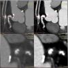
Case 1. Proximal Cap ambiguity of LAD CTO ( Figure 22 ).
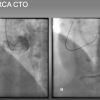
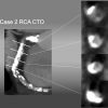
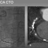
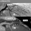
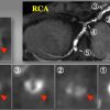
Case 2. Ambiguous proximal and distal cap and vessel course of RCA CTO ( Figure 23a and Figure 23b ).
Case 3. Ambiguous CTO vessel course of mid-RCA CTO ( Figure 24 ).
Case 4. Ambiguous proximal and distal caps of LAD CTO ( Figure 25 ).
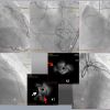
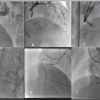
Case 5. Practical application of CCTA-Angiography co-registration of a short, but calcified mid LAD CTO ( Figure 26a, Figure 26b, Figure 26c ).
Case 6. Practical application of CCTA on heavily calcified, long, severely bent RCA CTO ( Figure 27a, Figure 27b, Figure 27c, Figure 27d and Figure 27e ).
CT Coronary angiography for CTO PCI
- Evaluates anatomical features not evident on a conventional invasive coronary angiogram: proximal cap ambiguity, true length of occlusion, the amount and distribution of the calcified plaques, distal vessel size, degree of remodeling, presence of collaterals and entire vessel course.
- Through the CT-RECTOR score can grade complexity and predict the feasibility of guidewire crossing
- The imaging protocol should include 3D Volume Rendering (VR), Multiple Reconstruction (MPR) and Maximum Intensity Projection (MIP)
Conclusion
As in any other medical procedure, understanding the procedural process is the first step of developing and acquiring the skill sets of complex PCI.
IVUS and CCTA are the ideal invasive and non-invasive tools, respectively, to define the anatomical key factors of CTO coronary intervention and navigate to choose the most appropriate next step. Although there is a lack of evidence to support their efficacy of scientific data and wide differences in clinical availability and device coverage in insurance, repeated application on various clinical setting can provide the operators to sharpen the skill-set of CTO-PCI and to enhance the procedural success rate without increasing risk of complications. The authors are of utmost pleasure when the chapter contributes further interest to all the doctors learning and practicing CTO-PCI.
Personal Perspective - Masahisa Yamane
Timely use of IVUS on CTO-PCI can not only inform the vessel anatomy ( proximal cap, reference vessel diameter, wire position in IP or SIS, dissection, and hematoma extension), but also help to choose the next step safely ( ADR, IVUS-navigated Re-entry, and reverse CART), enhancing the success rate and long-term durability(stent optimization after successful balloon dilation).
CCTA has the superior modality in detailing the calcification and vessel tortuosity, two of the major hindrance of contemporary PCI.
With a judicious application of imaging modalities and recent technological developments, we can further achieve the steady rise of procedural success rate without risking the patients.


