Summary
The patient selection and procedural planning for transcatheter structural interventions have been facilitated by the extensive use of multislice computed tomography (MSCT) multiplanar reconstruction. This imaging technique allows the identification of the optimal fluoroscopic viewing angles of left- and right-sided heart structures, in particular the aortic, mitral and tricuspid valve complexes. The use of standardised fluoroscopic viewing angles, during transcatheter interventions, can be extremely helpful in technically challenging scenarios (e.g., bifurcation stenting, mitral and tricuspid valve interventions). A better understanding of multimodality imaging of the heart chamber anatomy can reduce the procedural time, radiation dose, contrast volume, and complications during transcatheter valve interventions while providing guidance for the operators. In this chapter we aim to describe the anatomy of heart and the coronary arteries by integrating MSCT, fluoroscopy and echocardiography.
Introduction
Traditionally, percutaneous coronary interventions (PCI) are performed using well-recognized anatomical patterns based on familiar fluoroscopic viewing angles. Coronary angiography has indeed an excellent resolution, but its two-dimensional (2D) nature inherently limits its diagnostic accuracy due to foreshortening and overlap of structures [11. Di Mario C, Sutaria N. Coronary angiography in the angioplasty era: projections with a meaning. Heart. 2005;91:968–976. ]. Since the introduction of transcatheter structural heart therapies, cardiologists have become increasingly aware of the importance of understanding anatomical details of cardiac structures under fluoroscopy [22. Van Mieghem NM, Piazza N, Anderson RH, Tzikas A, Nieman K, De Laat LE, McGhie JS, Geleijnse ML, Feldman T, Serruys PW, Jaegere PP de. Anatomy of the mitral valvular complex and its implications for transcatheter interventions for mitral regurgitation. J Am Coll Cardiol. 2010;56:617–626. ]. Many critical anatomical structures comprise several spatial components arranged in a complex three-dimensional (3D) geometry. Even though these anatomical and functional components have been the topic of numerous publications [22. Van Mieghem NM, Piazza N, Anderson RH, Tzikas A, Nieman K, De Laat LE, McGhie JS, Geleijnse ML, Feldman T, Serruys PW, Jaegere PP de. Anatomy of the mitral valvular complex and its implications for transcatheter interventions for mitral regurgitation. J Am Coll Cardiol. 2010;56:617–626. ], little consideration has been given to understanding their configuration as appreciated under fluoroscopy [33. Cosío FG, Anderson RH, Kuck KH, Becker A, Borggrefe M, Campbell RW, Gaita F, Guiraudon GM, Haïssaguerre M, Rufilanchas JJ, Thiene G, Wellens HJ, Langberg J, Benditt DG, Bharati S, Klein G, Marchlinski F, Saksena S. Living anatomy of the atrioventricular junctions. A guide to electrophysiologic mapping. A Consensus Statement from the Cardiac Nomenclature Study Group, Working Group of Arrhythmias, European Society of Cardiology, and the Task Force on Cardiac Nomenclature from NASPE. Circulation. 1999;100:e31-7. ]. Understanding fluoroscopic cardiac anatomy can facilitate optimal positioning and deployment of prostheses during transcatheter valve repair/replacement, left atrial appendage occlusion, septal defect closure, paravalvular leak closure. Commonly, these therapies are conducted using standard fluoroscopic angulations irrespective of variations in anatomy. However, it is possible that patient-specific fluoroscopic viewing angles can improve procedural safety and efficacy.
Interestingly, the common chamber views appreciated on echocardiography can be appreciated across imaging modalities, including fluoroscopy, thereby providing the basis for a common language (i.e. imaging modality independent). Furthermore, optimal projection curves (i.e. S-curves) that provide fluoroscopic viewing angles of a structure in-plane or en-face can be interrelated with fluoroscopic chamber views. Understanding the relationship between chamber views and optimal projection curves is the fundamental principle in mastering “fluoroscopic anatomy” [44. Thériault-Lauzier P, Andalib A, Martucci G, Mylotte D, Cecere R, Lange R, Tchétché D, Modine T, Mieghem N van, Windecker S, Buithieu J, Piazza N. Fluoroscopic anatomy of left-sided heart structures for transcatheter interventions: insight from multislice computed tomography. JACC Cardiovasc Interv. 2014;7:947–957. , 55. Pighi M, Thériault-Lauzier P, Alosaimi H, Spaziano M, Martucci G, Xiong T-Y, Buithieu J, Ybarra LF, Afilalo J, Leipsic J, Ozden Tok O, Mousavi N, Mangiameli A, Pilgrim T, Praz F, Windecker S, Piazza N. Fluoroscopic Anatomy of Right-Sided Heart Structures for Transcatheter Interventions. JACC Cardiovasc Interv. 2018;11:1614–1625. , 66. Spaziano M, Thériault-Lauzier P, Meti N, Vaquerizo B, Blanke P, Deli-Hussein J, Chetrit M, Galatos C, Buithieu J, Lange R, Martucci G, Leipsic J, Piazza N. Optimal fluoroscopic viewing angles of left-sided heart structures in patients with aortic stenosis and mitral regurgitation based on multislice computed tomography. J Cardiovasc Comput Tomogr. 2016;10:162–172. ].
Multislice computed tomography (MSCT) multiplanar reconstruction of the aortic valvular complex has enhanced patient selection and procedural planning for transcatheter aortic valve replacement [77. Schultz C, Moelker A, Tzikas A, Piazza N, Feyter P de, Geuns RJ van, Serruys PW, Krestin GP, Jaegere P de. The use of MSCT for the evaluation of the aortic root before transcutaneous aortic valve implantation: the Rotterdam approach. EuroIntervention. 2010;6:505–511. ]. For example, MSCT affords physicians the opportunity to pre-select optimal x-ray fluoroscopic viewing angles for deployment of the valve prosthesis [88. Gurvitch R, Wood DA, Leipsic J, Tay E, Johnson M, Ye J, Nietlispach F, Wijesinghe N, Cheung A, Webb JG. Multislice computed tomography for prediction of optimal angiographic deployment projections during transcatheter aortic valve implantation. JACC Cardiovasc Interv. 2010;3:1157–1165. , 99. Dvir D, Kornowski R. Percutaneous aortic valve implantation using novel imaging guidance. Catheter Cardiovasc Interv. 2010;76:450–454. ]. The same principles can be applied for planning of any fluoroscopy-guided procedure, including coronary interventions. Such angle optimization may decrease procedure time, radiation exposure, and injected contrast agent volume [1010. Samim M, Stella PR, Agostoni P, Kluin J, Ramjankhan F, Budde RPJ, Sieswerda G, Algeri E, Belle C van, Elkalioubie A, Juthier F, Belkacemi A, Bertrand ME, Doevendans PA, Van Belle E. Automated 3D analysis of pre-procedural MDCT to predict annulus plane angulation and C-arm positioning: benefit on procedural outcome in patients referred for TAVR. JACC Cardiovasc Imaging. 2013;6:238–248. ]. It may reduce the risk of acute kidney injury [1010. Samim M, Stella PR, Agostoni P, Kluin J, Ramjankhan F, Budde RPJ, Sieswerda G, Algeri E, Belle C van, Elkalioubie A, Juthier F, Belkacemi A, Bertrand ME, Doevendans PA, Van Belle E. Automated 3D analysis of pre-procedural MDCT to predict annulus plane angulation and C-arm positioning: benefit on procedural outcome in patients referred for TAVR. JACC Cardiovasc Imaging. 2013;6:238–248. ] and paravalvular regurgitation [1111. Poon KK, Crowhurst J, James C, Campbell D, Roper D, Chan J, Incani A, Clarke A, Tesar P, Aroney C, Raffel OC, Walters DL. Impact of optimising fluoroscopic implant angles on paravalvular regurgitation in transcatheter aortic valve replacements - utility of three-dimensional rotational angiography. EuroIntervention. 2012;8:538–545. ].
The goal of this chapter is to provide knowledge regarding [11. Di Mario C, Sutaria N. Coronary angiography in the angioplasty era: projections with a meaning. Heart. 2005;91:968–976. ] the fluoroscopic chamber views of the right and left heart [22. Van Mieghem NM, Piazza N, Anderson RH, Tzikas A, Nieman K, De Laat LE, McGhie JS, Geleijnse ML, Feldman T, Serruys PW, Jaegere PP de. Anatomy of the mitral valvular complex and its implications for transcatheter interventions for mitral regurgitation. J Am Coll Cardiol. 2010;56:617–626. ] the optimal projection curves of the various cardiac structures (i.e. aortic, mitral and tricuspid valves, atrial septum, left atrial appendage) [33. Cosío FG, Anderson RH, Kuck KH, Becker A, Borggrefe M, Campbell RW, Gaita F, Guiraudon GM, Haïssaguerre M, Rufilanchas JJ, Thiene G, Wellens HJ, Langberg J, Benditt DG, Bharati S, Klein G, Marchlinski F, Saksena S. Living anatomy of the atrioventricular junctions. A guide to electrophysiologic mapping. A Consensus Statement from the Cardiac Nomenclature Study Group, Working Group of Arrhythmias, European Society of Cardiology, and the Task Force on Cardiac Nomenclature from NASPE. Circulation. 1999;100:e31-7. ] integration of this knowledge toward transcatheter structural heart interventions and [44. Thériault-Lauzier P, Andalib A, Martucci G, Mylotte D, Cecere R, Lange R, Tchétché D, Modine T, Mieghem N van, Windecker S, Buithieu J, Piazza N. Fluoroscopic anatomy of left-sided heart structures for transcatheter interventions: insight from multislice computed tomography. JACC Cardiovasc Interv. 2014;7:947–957. ] the relationship between chamber views and fluoroscopic projections of coronary arteries.
Bridging between cardiac imaging modalities: the need for a common terminology
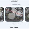
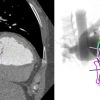
The use of a particular terminology to describe the heart impacts the way physicians describe the structures of the heart. Distinct anatomical terminologies are used by imagers using different imaging modalities. These dissimilarities are often experienced as a major obstacle during procedural planning and realisation. For instance, the mid-esophageal mitral commissural view on transeophageal echocardiographic, the vertical long-axis view on nuclear cardiac imaging and the right anterior oblique (RAO)/cranial projection on fluoroscopy all depict a two-chamber view of the left heart, showing the left atrium and left ventricle. In fact, the way the heart appears is a matter of viewing angle rather than imaging modality. A three-chamber view of the left heart, showing the left atrium, left ventricle and left ventricular outflow tract (LVOT)/aorta, can be obtained from an anatomical preparation of the heart as well as by echocardiography, fluoroscopy, MSCT or magnetic resonance imaging (MRI) as long as the heart is considered from a similar angle ( Figure 1). The use of a common “anatomy-centric” terminology, rather than “modality-centric” terminology, is thus mandatory to bridge the gaps across imaging techniques. The following principles may pave the way to a common multimodality terminology that will allow for an easier and more efficient interaction between imagers and operators in the catheterization laboratory.
Attitudinal description of heart anatomy
In our discussion, structures will be termed according to their attitudinally correct anatomical position [1212. Anderson RH, Loukas M. The importance of attitudinally appropriate description of cardiac anatomy. Clin Anat. 2009;22:47–51. ]. This implies that the subject is facing the observer and standing upright. Thus, structures closer to the observer are described as being anterior and those relatively farther away within the body are posterior. Components lying closer to the head are superior (i.e., cranial [CRA]) and those toward the feet are said to be inferior (i.e., caudal [CAU]). Structures to the left-hand side of the observer are right-sided and those to the observer’s right are left-sided.
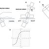
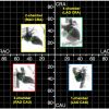
The fluoroscopic screen portrays the thorax in an upright orientation despite the patient being in a supine position. Superior and inferior structures are appreciated in the upper and lower halves of the screen. The direction of fluoroscopic projections is described based on 2 conventional angles, CRA/CAU and left anterior oblique (LAO)/right anterior oblique (RAO) (Figures 2A and 2B). In the anteroposterior viewing angle (CRA/CAU 0, LAO/RAO 0), right- and left-sided structures are found on the left and right sides of the screen, respectively. Of note, discussing heart structures in their attitudinal position is in perfect agreement with nomenclatures used for CT and x-ray fluoroscopic imaging ( Figure 3); this is not necessarily true with echocardiography.
Fluoroscopic anatomy using MSCT
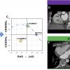
Fluoroscopy is used to guide the vast majority of transcatheter cardiac procedures. Inherently, it is a 2-dimensional imaging modality that requires the user to select a viewing angle that provides accurate information on device positioning. For a particular structure, an optimal viewing angle should minimize positioning errors due to parallax. The goal of many transcatheter procedures -such as valve implantations, left-atrial appendage occlusions, septal defect closures, and paravalvular leak occlusions - is to implant a quasicylindrical device inside a highly variable anatomical structure. The fluoroscopic projection that minimizes parallax during deployment is such that the source-to-detector direction is orthogonal to the axis of symmetry of the anatomical feature of interest ( Figure 2C). Based on this criterion, it is possible to determine an optimal CRA/CAU angle for any given LAO/RAO angle. The plot of the optimal combinations is called the optimal projection curve [8,10,13–15].
MSCT is a 3D imaging modality that is not affected by parallax. MSCT images can be used to define the direction of structures and produce an optimal projection curve ( Figure 2D). In addition to parallax errors, optimal view angles should also minimize the overlap of anatomic structures, a problem that also stems from the 2D nature of fluoroscopy. In the context of transcatheter interventions, some cardiac structures must be distinguished in order to accurately implant devices. The overlap of a highly attenuating anatomical structure with the region of implantation may reduce the contrast-to-noise ratio and compromise visualization. Therefore, it is crucial to understand which fluoroscopic angulations provide maximal separation between structures of interest. This understanding can be obtained from MSCT angiography, which depicts cardiac structures with relatively high soft-tissue contrast, as well as high temporal and spatial resolution.
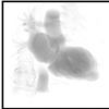
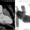
Fluoroscopy and MSCT share a common image contrast mechanism: x-ray attenuation Consequently, it is possible to use MSCT volumetric data to simulate fluoroscopic images. A ray-casting method based on this principle will be used to generate the fluoroscopic images presented in this chapter to demonstrate how MSCT may provide optimal fluoroscopic viewing angles for heart structures ( Figure 4). It is important to note that fluoroscopic angulations are dependent on the specific orientation of the heart within the thorax, a parameter that may vary considerably between patients [8,10,13–15]. Although we describe general angulations, exact angulations may be determined for a specific patient prior to an intervention. Measurement of fluoroscopic angulation from MSCT data can be done with visualization software packages that offer double-oblique multiplanar reconstruction; the exact CRA/CAU and RAO/LAO angulations for a particular structure can be obtained by analysing the oblique sagittal and oblique transverse views, respectively.
Heart chamber views as multimodality reference patterns
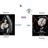
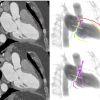
Recognition of heart chamber views is well established in echocardiography. The radiolucency of cardiac structures projected by fluoroscopy has accustomed interventional cardiologists to specific patterns of contrast-enhanced chambers and arteries while overlooking the global 3D cardiac structure. Chamber views of the heart, however, can be generated during fluoroscopy using specific C-arm angulations while exposing the operator to familiar anatomical patterns as those seen by other imaging modalities. As shown in Figure 4. a three-chamber view can be obtained by MSCT and translated into a fluoroscopic image; a similar 3-chamber view can be obtained by echocardiography.
Fluoroscopic anatomy in view of heart chambers
Simulation of fluoroscopic images based on MSCT volumetric data allows for generation of one (short axis), two, three or four chamber views of the left/right heart by fluoroscopy ( Figure 5). Of note, while MSCT generate 3D cross-sectional images, the fluoroscopic image is a 2D summation of cardiac structures depending on the angle of projection. Each left/right fluoroscopic chamber view can be characterized by specific anatomical structures that appear in perpendicular or en-face projections. Of note, two additional views of the right heart, the bicaval and right ventricle outflow-tract-pulmonary artery (RVOT-PA) views, can be achieved in extreme C-arm angulation for specific purposes [. ].
The fluoroscopic left heart
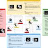
The regions of fluoroscopic angulations corresponding to each of the chamber views and the specific structures of interest of the left heart are shown in Figure 6 and Figure 7, respectively.
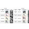
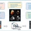
The main features of multimodality imaging of the left heart are summarised in Figure 8.
One-chamber (short-axis) view of the left heart
Short-axis view of the left ventricle can be obtained in a LAO projection with CAU angulation (average fluoroscopic angulation: LAO50°/CAU20°). It provides a clear separation of the aortic and mitral valves. This projection allows to evaluate the major and minor axes of both mitral and aortic valve annuli. Displaying the mitral valve en-face, the one-chamber view is useful for the guidance of procedure requiring separation of the anterior and posterior mitral valve leaflets and leaflets scallops. Interestingly, in the short-axis view, the major axis of the left atrial appendage ostium can be visualised in plane. The corresponding view on transthoracic echocardiography can be appreciated from the parasternal and subcostal short axes and on transoesophageal echocardiography from a transgastric short-axis 0° view.
Two-chamber view of the left heart
This view can be obtained with a shallow RAO projection with a variable degree of CRA angulation (average fluoroscopic angulation: RAO30°/CRA15°). It allows to appreciate the major axis of the aortic and mitral valves annulus. Two-chamber view is useful to separate the anterior (A1, A2, A3) and posterior (P1, P2, P3) mitral leaflets scallops. Of note, due to the 2D nature of fluoroscopy, each A-P paired scallops (i.e. A1-P1, A2-P2 and A3-P3) appear overlapped, differently from the corresponding echocardiographic commissural view. On transoesophageal echocardiography, two-chamber view can be appreciated from a mid-esophageal 90° or transgastric long-axis 90° view.
The fluoroscopic left heart two-chamber view provides maximum separation between papillary muscles, which could facilitate operators in avoiding these structures while advancing catheters into the left ventricle. This view also displays atrial septum nearly in plane, which can be useful for trans-septal punctures. Finally, this projection allows the operators to appreciate left atrial appendage separated from left superior pulmonary vein.
Three-chamber view of the left heart
Setting a three-chamber view, which can be obtained in a steep RAO projection with a variable degree of CAU angulation, both the aortic valve and mitral valve annulus appear in plane, with a clear separation of LVOT/aortic annulus from the mitral valve (average fluoroscopic angulation: RAO60°/CAU45°).
By positioning the C-arm in an extreme RAO projection with a moderate CAU angulation (average angulation: RAO 70°/CAU 50°) the operator can visualise the minor axis of the aortic valve. This view can be useful for the sizing of the balloon used for pre-dilatation of the valve or plain balloon aortic valvuloplasty. The major axis of the aortic annulus is provided by a mild LAO projection with a minimal CRA/CAU angulation. The three-chamber view also demonstrates an en-face view of the atrial septum and the left atrial appendage ostium. The fluoroscopic three-chamber fluoroscopic view corresponds to the parasternal long-axis or apical three-chamber view on transthoracic echocardiography. Similar views can be obtained from a mid-esophageal long-axis 120°-140° or transgastric long- axis 110°-130° view by transoesophageal echocardiography.
Four-chamber view of the left heart
Four-chamber view can be obtained by placing the fluroscopic C-arm in a LAO projection with cranial angulation (average fluoroscopic angulation: LAO10°/CRA60°). Four-chamber view corresponds to the fluoroscopic angulation where both mitral valve annulus and atrial septum are in plane. This view displays full separation between left- and right-ventricles and atria and sets ventricular and atrial septa in plane. The aortic and mitral valves are superimposed and the mitral valve leaflets and scallops appear overlapped. The fluoroscopic 4-chamber view corresponds to the classical apical 4-chamber view on transthoracic echocardiography or mid-to-low esophageal view at 0°-20° on transoesophageal echocardiography.
- Left-sided heart structures can be described by using 1,2,3 and 4 chamber views;
- Although fluoroscopic views can potentially differ between patients, average angulations can be established for description of left-sided heart structures;
- Standard or modified echocardiographic views mimicking fluoroscopic chamber views can be obtained by both transthoracic and transoesophageal echocardiography.
- The fluoroscopic right heart
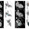
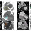
The regions of fluoroscopic angulations corresponding to each of the chamber views of the right heart are shown in Figure 9. Co-registration of MSCT and fluoroscopic of main right heart structures is shown in Figure 10.
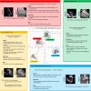
The main features of multimodality imaging of the right heart are summarised in Figure 11.
One-chamber (short-axis) view of the right heart
The one-chamber (short-axis) view of the right heart displays the en-face view of the tricuspid valve and it can be obtained in a LAO projection with a variable degree of CAU angulation (average fluoroscopic angulation: LAO55°/CAU15°). In this view, it is possible to appreciate the trajectory of the coronary sinus. It is also useful for targeting the structures of interest by matching the anatomic disposition of the tricuspid leaflets of the fluoroscopic view with a modified (upside down) transgastric transesophageal echocardiography view, seen from the ventricular side. The one-chamber view can be obtained using a basal transgastric window (0°-20°) on transesophageal echocardiography evaluation, tor by using echocardiographic 3D acquisitions during transthoracic or echocardiography or transesophageal echocardiography [. ].
Two-chamber (right ventricle inflow) view of the right heart
A two-chamber (right ventricle inflow) view of the right heart can be obtained by RAO projection with a variable degree of CAU angulation (average fluoroscopic angulation: RAO60°/CAU50°). This view can be potentially helpful to identify the attachments of the anterior and posterior leaflets of the tricuspid valve to the atrioventricular junction and to maximally separate the anterior and posterior papillary muscles, in order to help operators to avoid entrapment in the subvalvular structures while attempting to navigate into the right ventricle.
Setting a mild CAU angulations, both the orifice of the inferior vena cava (IVC) and the tricuspid valve appear in plane and this allows to better understand the precise angle between the planes of these two structures and to guide delivery catheters from the IVC across the tricuspid valve and into the right ventricular inflow tract.
During attempts to enter the right ventricle, caution is needed to avoid entering and/or injuring the coronary sinus, whose orifice is at 90 degrees with the tricuspid valve annulus. Using a fluoroscopic RAO projection with CAU angulation permit to achieve maximal separation between the coronary sinus and the tricuspid valve, while both structures are in plane ( Figure 12).
The two-chamber view of the right heart corresponds to a transthoracic echocardiographic parasternal long-axis two-chamber view of the right ventricle. Transesophageal echocardiography can display a similar two-chamber view in a mid-esophageal right ventricular inflow view at 100°-120° (bicaval angle, rotated toward the right), a low-esophageal right atrial view, or a transgastric right ventricular inflow (long-axis) view at 110°-130°.
Three-chamber (right ventricle inflow) view of the right heart
This view is obtained by placing the C-arm in a RAO projection with a variable degree of CRA angulation (average fluoroscopic angulation: RAO25°/CRA15°). With a mild CRA angulation and the tricuspid valve in plane it is possible to appreciate the attachments of the posterior and septal leaflets. This view allows to appreciate the ostium of the coronary sinus en-face. On transesophageal echocardiography, the right-heart three-chamber view corresponds to a transgastric view at 60°-90°.
Four-chamber (right ventricle inflow) view of the right heart
This view can be obtained by placing the C-arm in a LAO (or a minimal RAO) projection with cranial angulation (average fluoroscopic angulation: LAO5°/CRA60°). An extreme cranial angulation with the tricuspid valve in plane allows operators to appreciate the attachments of the anterior and septal leaflets. The four-chamber view displays the tricuspid valve annulus and atrial septum both in plane. The fluoroscopic four-chamber view corresponds to the classical apical four-chamber view on transthoracic echocardiography or mid-to-low esophageal view at 0°-20° on transesophageal echocardiography.
Bicaval and right ventricle outflow tract (RVOT)-pulmonary artery view
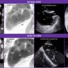
Two adjacent tomographic views can be superimposed on fluoroscopy by placing the C-arm in a LAO moderate-to-extreme (lateral) projection with a variable degree of CRA/CAU angulation: the RVOT-pulmonary artery view (medially) and the bicaval view (more laterally). Likewise, this structure is best appreciated on the mid-esophageal bicaval view on transesophageal echocardiography where it is identified from the confluence of the superior vena cava and the body of the right atrium ( Figure 13 - upper purple panel).
During transcatheter pulmonary valve re-placements, physicians often select a lateral projection with shallow CRA angulation to obtain the best views of the right ventricle-to-pulmonary artery tract ( Figure 13 - lower purple panel). Similar transesophageal echocardiographic views can be obtained from a high transesophageal window at 0° or from a deep transgastric window at 70°-90°. Oriented more to the right, the bicaval view can be appreciated from a modified subcostal transthoracic view or from the classical mid- transesophageal bicaval view at 90°-110°.
- Right-sided heart structures can be described by using 1,2,3 and 4 chamber views;
- Two additional chamber views obtained in extreme LAO (lateral) views (i.e., bicaval and RVOT-PA chamber views) can be useful to visualize the atrial septum in plane and the right ventricular outflow tract;
- Standard or modified echocardiographic views mimicking fluoroscopic chamber views can be obtained by both transthoracic and transoesophageal echocardiography.
Optimal projection curves: toward individualized fluoroscopic anatomy
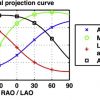
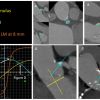
While fluoroscopic chamber views might facilitate pattern recognition for structural interventions, the orientation of cardiac structures can vary somewhat amongst patients. Nonetheless, cardiac structures, similar to coronary arteries, can be found in consistent fluoroscopic quadrants across patients. The utilization of 3D tomographic images for procedural planning allows per-patient individualized mapping of cardiac structures. Accordingly, specific fluoroscopic working angles might be planed based on anatomical and procedural characteristics. As mentioned above, an optimal fluoroscopic angle is such that the vector joining the x-ray source and the detector is orthogonal to the vector of the structure of interest (i.e. the en-face/axial view of the structure). Each CRA/CAU angulation of the C-arm can be adjusted by a corresponding RAO/LAO angulation maintaining orthogonality with the structure of interest. The optimal projection curve is a S-shaped curve consisting of continuous pairs of optimal C‐arm angulations for a given structure. Optimal projection curves can be calculated by designated software for any cardiac structure using the following mathematical model described in Figure 14 [1313. Tzikas A, Schultz C, Van Mieghem NM, Jaegere PPT de, Serruys PW. Optimal projection estimation for transcatheter aortic valve implantation based on contrast-aortography: validation of a Prototype Software. Catheter Cardiovasc Interv. 2010;76:602–607. ]. Optimal projection curves differ from one structure to another depending on spatial orientation ( Figure 15). Of note, the point of intersection between two S-curves represents C-arm coordinates in which the two structure are projected in plane.
Optimal projection curves are commonly used during planning of transcatheter aortic valve replacement (TAVR). Tracing of the aortic annulus plane on MSCT in its en-face/axial view permits instant generation of the annular optimal projection curve by automated software. The S-curve will provide the operator will all the viewing angles in which the aortic annulus appears in plane, which is crucial for appropriate estimation of the implantation depth of the valvular prosthesis. A similar approach can be adopted for any intervention that consist of device placement into an anatomical structure [e.g. left atrial appendage closure (LAAC), transcathehter mitral/pulmonary valve replacement, etc.].
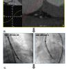
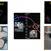
The concept of optimal projection curves can be used not only for anatomical structures but in fact for any structure projected under fluoroscopy, including delivery catheters or cardiac devices. As mentioned above, one en-face view or two perpendicular views are required to generate an optimal projection curve. Thus, two perpendicular fluoroscopic views can be used to generate an optimal projection curve of a delivery catheter or cardiac device during a procedure. For example, this approach can be effective during TAVR with self-expandable devices. The intersection between the optimal projection curves of the aortic annulus (i.e. as measured by pre-procedural MSCT) and that of the annular marker of the delivery catheter annular marker during the procedures will provide a specific “double S-curve” viewing angle in which both the aortic annulus and delivery catheter are in plane without parallax. Such a view is thus optimal for device positioning and estimation of implantation depth ( Figure 16). Eventually, optimal working angles in the catheterization laboratory can be calculated and planned before and during the procedure in order to optimize procedural course and minimize procedural time, radiation exposure, contrast agent administration and complications.
Cardiac structures with similar orientations in the body (e.g. mitral and tricuspid valve or atrial appendage and atrial septum) will have similarly shaped S-curves. Furthermore, S-curves intersect only 3 of the 4 quadrants – the non-intersecting quadrant defines the structure en-face while the 3 intersecting quadrants have the structure in plane. The distance between 2 structures’ S-curves describes the relative angle between the planes of the 2 structures. Thus, 2 structures with overlapping S-curves lie in the same plane. On the other hand, 2 structures with S-curves at right angle, would suggest that the 2 planar structures lie at 90 degrees to each other.
Fluoroscopic anatomy implications for transcatheter interventions
Chamber anatomy for aortic valve interventions
The aortic root is the continuation of the left ventricular outflow tract, extending from the basal attachment points of the aortic valve leaflets to their peripheral attachment at the level of the sinotubular junction [1212. Anderson RH, Loukas M. The importance of attitudinally appropriate description of cardiac anatomy. Clin Anat. 2009;22:47–51. ]. It is made of three components: 1) the valvular leaflets; 2) the fibrous interleaflet triangles; and 3) the sinuses of Valsalva. The three leaflets form the limits of the right, left, and non-coronary aortic sinuses. To obtain an optimal fluoroscopic view of the aortic root it has to be perpendicular to the plane of the aortic annulus. While performing transcatheter aortic valve replacements (TAVR), physicians focus on two main points: the virtual plane of the aortic valve annulus and the relative position of the sinuses of Valsalva.
The aortic valve annulus is defined as the planar ring of tissue that unites the basal attachment points of the three aortic valve leaflets. Rarely circular [1717. Piazza N, Jaegere P de, Schultz C, Becker AE, Serruys PW, Anderson RH. Anatomy of the aortic valvar complex and its implications for transcatheter implantation of the aortic valve. Circ Cardiovasc Interv. 2008;1:74–81. ], the annulus presents a long and a short axis that can be appreciated using MSCT [1818. Schultz CJ, Moelker A, Piazza N, Tzikas A, Otten A, Nuis RJ, Neefjes LA, Geuns RJ van, Feyter P de, Krestin G, Serruys PW, Jaegere PPT de. Three dimensional evaluation of the aortic annulus using multislice computer tomography: are manufacturer’s guidelines for sizing for percutaneous aortic valve replacement helpful? Eur Heart J. 2010;31:849–856. ]. Using a 2D imaging technique, such as fluoroscopy, the apparent diameter of the aortic annulus varies depending on the view angle used by the operator.
The minor axis can be visualized in a three-chamber view (extreme RAO, moderate CAU), particularly helpful for sizing the balloon used for predilatation of the valve or plain balloon aortic valvuloplasty. Conversely, the two-chamber view, obtained with mild LAO projection and minimal CRA/CAU angulation, provides the major axis of the aortic valve. During TAVR, particular attention is required in selecting a view that shows the right coronary sinus between the non-coronary and left coronary sinuses in order to visualize the aortic annulus in plane and to obtain correct placement of the aortic prosthesis. While performing TAVR, particular interest is often directed towards selecting a view showing the right coronary sinus between the non-coronary and left coronary sinuses to obtain a projection of the aortic annulus in plane and to achieve correct placement of the prosthesis. This view is obtained using a minimal LAO projection with minimal CRA/CAU angulation (average angulation: LAO10°/CRA0°) [1919. Pighi M, Thériault-Lauzier P, Piazza N. Multimodality imaging for interventional cardiologists. EuroIntervention. 2018;14:AB33-AB39. ].
Chamber anatomy for mitral valve interventions
Potential useful chamber views and fluoroscopic angulations for the guidance of transcatheter procedures targeting the mitral valve are summarized in Table 1.
The mitral valve has 2 major leaflets commonly described as being anterosuperior (or aortic) and posteroinferior (or mural) [1919. Pighi M, Thériault-Lauzier P, Piazza N. Multimodality imaging for interventional cardiologists. EuroIntervention. 2018;14:AB33-AB39. ]. The Carpentier classification recognizes 3 scallops in the mural leaflet (P1 to P3) and 3 corresponding segments in the aortic leaflet (A1 to A3) [2020. Carpentier A. Cardiac valve surgery--the “French correction”. J Thorac Cardiovasc Surg. 1983;86:323–337. ]. According to an attitudinal approach and using the central segment (A2P2) as reference, the A1P1 and A3P3 portions of the valve are located superoposterior and inferoanterior, respectively [1919. Pighi M, Thériault-Lauzier P, Piazza N. Multimodality imaging for interventional cardiologists. EuroIntervention. 2018;14:AB33-AB39. ].
Emerging mitral valve transcatheter interventions require the positioning of the delivery catheter and device in a precise position relative to each leaflet and each segment. Recognizing the leaflet configuration in fluoroscopic chamber-view may facilitate this process.
A three-chamber view (extreme RAO/CAU view) provides maximum separation between the mural and aortic leaflets of the mitral valve. However, in this view the both the aortic segments and the mural segments overlap one another. Two-chamber view (RAO/CRA view) allows physicians to achieve separation of the leaflet segment [11. Di Mario C, Sutaria N. Coronary angiography in the angioplasty era: projections with a meaning. Heart. 2005;91:968–976. , 22. Van Mieghem NM, Piazza N, Anderson RH, Tzikas A, Nieman K, De Laat LE, McGhie JS, Geleijnse ML, Feldman T, Serruys PW, Jaegere PP de. Anatomy of the mitral valvular complex and its implications for transcatheter interventions for mitral regurgitation. J Am Coll Cardiol. 2010;56:617–626. , 33. Cosío FG, Anderson RH, Kuck KH, Becker A, Borggrefe M, Campbell RW, Gaita F, Guiraudon GM, Haïssaguerre M, Rufilanchas JJ, Thiene G, Wellens HJ, Langberg J, Benditt DG, Bharati S, Klein G, Marchlinski F, Saksena S. Living anatomy of the atrioventricular junctions. A guide to electrophysiologic mapping. A Consensus Statement from the Cardiac Nomenclature Study Group, Working Group of Arrhythmias, European Society of Cardiology, and the Task Force on Cardiac Nomenclature from NASPE. Circulation. 1999;100:e31-7. ]. In this view, mural and aortic leaflets overlap such that A1 overlaps P1, A2 overlaps P2, and A3 overlaps P3 ( Figure 17).
The mitral annulus has a maximum diameter (or intercommissural diameter), and a minimum diameter (or aortomural diameter). The sizing of the mitral annulus is important because the design of some transcatheter mitral valve replacement devices are not axially symmetric and must be positioned at a particular angle relative to the mitral commissure.
The intercommissural diameter can be obtained using a two-chamber view (mild RAO/CRA), which also provides maximal separation of papillary muscles. Conversely, the aortomural diameter of the mitral annulus can be appreciated in a three-chamber view (extreme RAO/CAU).
In the three-chamber view the aortic-mitral curtain, the area of fibrous continuity between the right and left trigones, is observed perpendicularly and clearly separated from the left atrium and the aortic root. This fluoroscopic projection could be of interest during transcatheter mitral valve bioprostheses implantation. Indeed, it can be helpful to evaluate the interaction between the prosthesis and the left ventricular outflow tract (LVOT), particularly to assess the potential risk of LVOT obstruction or a deformation of the aortic-mitral curtain [44. Thériault-Lauzier P, Andalib A, Martucci G, Mylotte D, Cecere R, Lange R, Tchétché D, Modine T, Mieghem N van, Windecker S, Buithieu J, Piazza N. Fluoroscopic anatomy of left-sided heart structures for transcatheter interventions: insight from multislice computed tomography. JACC Cardiovasc Interv. 2014;7:947–957. ].
Papillary muscles lie in the posterior-half of the left ventricular cavity, and are described as inferoanterior and posterosuperior, according to attitudinal description. Their exact number, positioning, morphology, and thickness can vary considerably [2121. Delgado V, Kapadia S, Marsan NA, Schalij MJ, Tuzcu EM, Bax JJ. Multimodality imaging before, during, and after percutaneous mitral valve repair. Heart. 2011;97:1704–1714. ]. Indeed, it is important to appreciate their fluroscopic configuration, because they could be potential obstacles to the deployment of transcatheter devices especially if their structures protrude into the left ventricle, such as mitral valve prostheses or ventricular septal defect closure devices.
- The use 1,2,3 and 4 chamber views enable the operator in navigating the left side of the heart and targeting specific structures for transcatheter interventions;
- Intraprocedural use of MSCT-derived fluoroscopic angulations can particularly useful for the guidance of complex transcatheter procedures (e.g., edge-to-edge mitral valve repair, transcatheter mitral valve annuloplasty).
- Atrial septum and transseptal puncture
The fossa ovalis is a depression in the right atrial aspect of the interatrial septum. Structures surrounding the atrial septum include: 1) the inferior vena cava (right inferior-posterior); 2) the infolding of the atrial septum (right superior-posterior); 3) the coronary sinus (left anterior-inferior); and 4) the noncoronary cusp of the aortic valve (left superior-anterior) [2222. Klimek-Piotrowska W, Hołda MK, Koziej M, Piątek K, Hołda J. Anatomy of the true interatrial septum for transseptal access to the left atrium. Ann Anat. 2016;205:60–64. ].
In recent years, the emerging percutaneous transcatheter therapies of valvular and congenital heart disorders have led to the widespread adoption and further modification of the transseptal (TSP) technique, to gain access to the left atrium, from the right side of the heart.
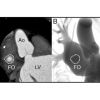
In the normal heart, the interatrial septum extends from a right posteroinferior to left anterosuperior direction, resulting in a right anterior oblique (RAO)/CAU “en face” ( Figure 18). The 4-chamber view can appreciate the atrial septum in plane, with the full separation of the left and right atria ( Figure 20).
A RAO/CRA (right heart 3-chamber/ short-axis) view displays the atrial septum with minimal overall with the aortic root, which lies left and anterior to de septum. This fluoroscopic view is of potential use to confirm the position of the transseptal needle over the septum.
Tricuspid valve
The TV represents a main focus of interest among right-sided heart structures and target for transcatheter interventions. A transcatheter repair or replacement device may require a specific chamber view that provides the annulus in plane along with other structures of interest. The optimal projection curve of the tricuspid valve annulus spans across LAO/CRA, RAO/CRA and RAO/CAU with a characteristic steep slope in the RAO region. The region not spanned by the curve provides the en-face view of the structure (i.e. LAO/CAU). The plane of the tricuspid annulus can be appreciated in 2-, 3- or 4-chamber view (RAO/CAU, RAO/CRA, LAO/CRA, respectively). Potential useful chamber views and fluoroscopic angulations for the guidance of transcatheter procedures targeting the tricuspid valve are summarized in Table 1.
The 1-chamber (or short-axis) view is useful to navigate catheters towards the anterior, posterior or septal leaflet of the tricuspid valve. Given that the right coronary artery (RCA) runs along the tricuspid valve annulus, the 1-chamber view can provide useful information about the spatial relationship between the RCA and tricuspid annulus. This view (“en-face” view of the tricuspid annulus) is essential when performing transcatheter annuloplasty of the tricuspid annulus as it allows to appreciate the relationship between the anchors and the artery.
The 2-chamber view of the right heart provides maximum separation between papillary muscles and it is potentially useful to avoid entrapment in the subvalvular structures and permits to safely achieve the positioning of specific devices in the right ventricular apex. It also provides the coronary sinus and tricuspid valve both in plane thereby mitigating parallax between these 2 structures and can facilitate cannulation of the coronary sinus (vs. tricuspid annulus). In this view, a transseptal needle will be “looking into the screen” with the atrial septum en-face. Furthermore, the 2-chamber view separates the anterior and posterior tricuspid valve leaflets similar to echocardiography ( Figure 11).
The 3-chamber view of the right heart provides a long-axis view of the right ventricle and is similar to the 3-chamber view of the left heart with respect to elongating the ventricular outflow tract and overlapping papillary muscles. In the 3-chamber view, the tricuspid and pulmonary valves can be found in plane; given that the right ventricular outflow tract is elongated, this view can be useful during transcatheter tricuspid or pulmonary valve replacement. Because this view separates the posterior and septal tricuspid valve leaflet, it can guide clip orientation during posterior-septal leaflet approximation ( Figure 11). The 3-chamber view has the coronary sinus en-face, which should be discouraged during cannulation procedures of the coronary sinus.
The 4-chamber view of the right heart can be obtained with the atrial septum and tricuspid valve annulus both in plane. The atrial and ventricular septum can be clearly visualized; this can be a useful view during ventricular septal defect closure or pacemaker positioning against the ventricular septum. The majority of tricuspid clip procedures aim to approximate the anterior and septal tricuspid valve leaflets. Because the 4-chamber view separates the anterior and septal tricuspid valve leaflets, it can complement echocardiography during clip orientation ( Figure 11).
- The use 1,2,3 and 4 chamber views enable the operator in navigating the right side of the heart and targeting specific structures for transcatheter interventions;
- Intraprocedural use of MSCT-derived fluoroscopic angulations can particularly useful for navigating the right ventricle and and guiding transcatheter procedures targeting the tricuspid valve (e.g., edge-to-edge tricuspid valve repair, transcatheter tricuspid valve annuloplasty).
Fluoroscopic anatomy in coronary interventions – back to the future with a third dimension
Invasive coronary angiography (ICA) has excellent resolution and remains the gold standard of coronary imaging since the late 1970s [2323. Ryan TJ. The coronary angiogram and its seminal contributions to cardiovascular medicine over five decades. Circulation. 2002;106:752–756. ]. Meanwhile, fluoroscopy holds several important drawbacks. First, the inert dependency on contrast agent radiopacity for visualization of structures has accustomed operators to focus on contrast-enhanced vessels, while ignoring the underlying heart wall/structures. Second, fluoroscopy has historically been performed using a limited set of routine viewing angles as “one-size-fits-all” approach, which is frequently suboptimal in patients with anatomic variations or disease-specific remodelling. Third, the 2D nature of fluoroscopy often hampers estimation of vessel calibre and length due to parallax/foreshortening. In addition, vessels overlap frequently impedes optimal assessment of arteries/branches. These pitfalls may result in misdiagnosis of the severity of coronary artery disease (CAD) or cause geographic miss during interventions leading to target vessel revascularization, especially in those cases of coronary ostial or bifurcation stenting. Pre-procedural coronary assessment by 3D tomography might help to overcome the limitations of fluoroscopy by providing crucial information regarding coronary anatomy and optimal strategy of percutaneous coronary intervention (PCI). In the current section we describe the fluoroscopic coronary anatomy in light of chamber views and discuss potential implications of 3D imaging in the planning of fluoroscopy-guided coronary interventions.
Coronary anatomy and fluoroscopic chamber views
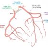
Fluoroscopic chamber views can be used as reference patterns for description of the coronary tree anatomy. Correct perception of the relation between angiographic coronary patterns and associated cardiac walls/structures might allow for better understanding of the applications of specific fluoroscopic angles during diagnostic and interventional procedures. Attitudinally, the coronary tree sprawls on an atrioventricular/short-axis, extending rightward and inferiorly, and an interventricular/long-axis, extending leftward and inferiorly ( Figure 21). An orthogonal projection of these two axes can be obtained by a cardiac four-chamber view across imaging modalities, including fluoroscopy (LAO/CRA). In this view, the left anterior descending (LAD) artery is seen elongated running within interventricular groove toward the apex. The left circumflex and right coronary arteries circumvent the mitral and tricuspid annuli, respectively, within the atrioventricular groove which appear in plane. Obtuse marginal branches from the circumflex artery and acute marginal branches from the right coronary artery (RCA) run inferiorly and supply the lateral walls of the left and right ventricle, respectively.
The cardiac atrioventricular/short axis can be projected in one chamber or “spider” view (LAU/CAU). In this view the left main coronary artery (LMCA) originating from the left coronary sinus appears elongated and its bifurcation into the LAD artery and circumflex arteries can be properly appreciated. The mitral and tricuspid annuli appear en-face circumvented by the left circumflex artery and RCA within the atrioventricular groove. Vessels with a course toward the apex, along the interventricular axis - the left anterior descending (LAD) artery, its diagonal branches and the obtuse marginals of the circumflex artery - appear with various degree of foreshortening ( Figure 22).
A mirror image of the LAD/circumflex arteries pattern obtained in one chamber view can be obtained in an opposite projection (RAO/CRA) on a two-chamber view of the left heart ( Figure 23). In this view it is the LAD that is seen fully elongated in its course along the anterior wall while the circumflex artery is foreshortened within the atrioventricular groove. From this view a caudal rotation toward the three-chamber view will separate the aortic and mitral valve and elongate the course of the circumflex artery and its marginal branches. The three-chamber view of the left heart display the LAD along the anteroseptal wall, well separated from the circumflex artery which run an orthogonal course toward the inferolateral wall ( Figure 24).
Optimal fluoroscopic projections for coronary interventions
Optimal fluoroscopic projections during ICA should minimize parallax/foreshortening of the aorto-coronary ostia and coronary vessels in order to provide the operators with accurate information about the caliber and length of the evaluated vessel. In addition, vessel overlap should be minimized by “separating” the segment of interest from adjacent branches. Optimal viewing angle is often challenging to achieve, especially while assessing coronary ostia and bifurcations. Suboptimal viewing angles may lead to an increase in procedural time, contrast agent administration and radiation exposure from one hand and to non-favorable procedural results from the other.
Planning of optimal working angles for coronary interventions: the role of computed tomography coronary angiography (CTCA)
Improvements in acquisition and reconstruction technology propelled the use of coronary computed tomography angiography (CCTA) as a first-line diagnostic tool for management of patients with suspected coronary artery disease (CAD). Less commonly recognized, is the concept of exploiting “au maximum” the 3D CTCA volume dataset to better inform the interventional cardiologist on “how to perform” the percutaneous coronary intervention (PCI). CCTA may allow for optimal selection of vascular access, fluoroscopic viewing angles, PCI strategy and adequate equipment, while preventing ICA-associated technical errors and potential sequelae ( Figure 25). Importantly, CCTA has the potential to reduce patient contrast load, radiation exposure and procedure times, and has been demonstrated to be cost-effective when appropriately incorporated into clinical workflows. While further studies are in need to establish the role of CCTA as interventional tool, it is reasonable that in the near future CCTA will replace ICA not only in CAD diagnosis, but also in PCI guidance.
Recommendations for the most appropriate fluoroscopic views for PCI are mostly empirical and lack an evidence-based approach [11. Di Mario C, Sutaria N. Coronary angiography in the angioplasty era: projections with a meaning. Heart. 2005;91:968–976. ]. Apart from CAD severity, CCTA offers crucial 3D anatomical information that can potentially dictate optimal working angles for interventions. This information might also guide selection of adequate equipment for intervention (e.g. guiding catheter shape, guidewire type and number, balloon/stent size and length, need for atherectomy), as well as optimal PCI strategy based on lesion characteristics (e.g. culprit artery localization, 1- vs. 2 stent bifurcation stenting, chronic total occlusions). The contribution of CCTA might be of particular importance while intervening in ostia of coronary arteries and proximal bifurcations. Eventually, though yet to be determined, CTCA may potentially improve the clinical outcomes of coronary interventions.
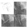
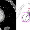
Planning of optimal working angles for coronary interventions by CCTA is based on the same principles learned from planning of structural heart interventions (e.g. TAVI, LACC). First, two perpendicular cross-sections of the evaluated coronary segment should be identified. Then, optimal projection curve of each one of the identified planes is generated by automated software. Finally, the intersection point between the two S-curves should provide the operator with a viewing angle that will minimize parallax/foreshortening of the vessel ( Figure 26). For example, the coordinates of intersection between the optimal projection curves of the ostial LAD and the proximal LAD (~8mm distal to the ostium) should provide an optimal viewing angle for stenting of the ostial LAD. Likewise, for ostial LMCA stenting, the intersection between the optimal projection curves of the aortic annulus and of the ostial LMCA should provide an optimal viewing angle in which the aortic root is fully elongated and the LMCA appears in a perpendicular plane. For coronary bifurcation stenting, optimal angles can be generated by creating a 3-point closed spline involving (a) the proximal main branch, (b) the distal main branch and (c) the side branch and subsequently calculating the en-face fluoroscopic viewing angle of that spline ( Figure 27). The en-face viewing angle of this plane provides optimal assessment of the bifurcation geometry ( Figure 28). Figure 18 describes the average optimal viewing angles for stenting of coronary ostia and bifurcations based on a retrospective analysis of 100 consecutive patients who underwent CTCA for suspected CAD. As the frequency of use of diagnostic CTCA increases in the near future, it has the potential to provide additional information for planning and guiding PCI procedures based on 3D tomographic dataset.
- Invasive coronary angiography is limited by the two-dimensional nature of fluoroscopy;
- Fluoroscopic coronary anatomy should be assessed in correlation with underlying cardiac wall and structure, using cardiac chambers view as reference patterns;
- As the frequency of use of diagnostic CTCA increases, it has the potential to provide additional information for planning and guiding coronary procedures based on 3D tomographic dataset.
Personal Perspective
Historically, knowledge about fluoroscopic anatomy was acquired through anecdotal experience. Sub optimal fluoroscopic viewing angles are often underappreciated and can lead to significant foreshortening and parallax of cardiac structures with adverse effects on the evaluation and/or percutaneous intervention. Furthermore, classic teaching in interventional cardiology has been based on pattern recognition. With the introduction of multislice computed tomography for structural heart interventions, the idea of patient specific viewing angles has gained widespread acceptance. The current chapter provides a foundational approach to mastering fluoroscopic anatomy for both transcatheter structural and coronary interventions. This approach relies on the concepts of chamber views, that can be obtained in various fluoroscopic quadrants, and optimal projection curves that allow us to understand the en-face or planar view of a given structure. Combining fluoroscopic chamber views and optimal projection curves, we can better understand the location and relative position of cardiac structures. While we progress towards a mastering of fluoroscopic anatomy we will inevitably eliminate the need to base our teaching solely on pattern recognition. Behind each catheter injection, lies a chamber view.


